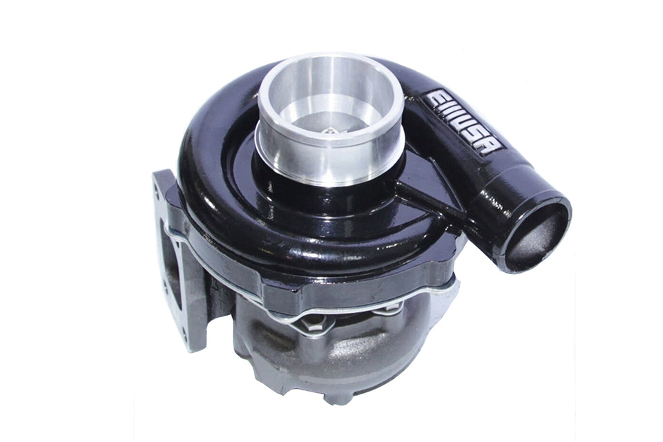
The Definition of Turbocharger
A/R
A/R describes a geometric property of all compressor and turbine housings. Increasing compressor A/R optimizes the performance for low boost applications. Changing turbine A/R has many effects. By going to a larger turbine A/R, the turbo comes up on boost at a higher engine speed, the flow capacity of the turbine is increased and less flow is wastegated, there is less engine backpressure, and engine volumetric efficiency is increased resulting in more overall power.
Choke Line
The choke line is on the right-hand side of a compressor map and represents the flow limit. When a turbocharger is run deep into choke, turbo speeds will increase dramatically while compressor efficiency will plunge (very high compressor outlet temps), and turbo durability will be compromised.
CHRA
Center housing rotating assembly - The CHRA includes a complete turbocharger minus the compressor, turbine housing, and actuator.
Clipped Turbine Wheels (Cut Back Turbine Blades)
When an angle is machined on the turbine wheel exducer (outlet side), the wheel is referred to as being ‘clipped’. Clipping causes an increase in the turbine wheel’s flow capability as it reduces backpressure in the turbine housing. However, it dramatically lowers the turbo efficiency at low speeds. This reduction causes the turbo to come up on boost at a later engine speed (increased turbo lag). High-performance applications should only use a clipped turbine wheel where outright power is the prerequisite. All Garrett GT turbos use modern unclipped wheels.
Corrected Airflow
Represents the corrected mass flow rate of air, taking into account air density (ambient temperature and pressure)
Example:
- Air Temperature (Air Temp) - 60°F
- Barometric Pressure (Baro) – 14.7 psi
- Engine air consumption (Actual Flow) = 50 lb/min
- Corrected Flow= Actual Flow Ö([Air Temp+460]/545) Baro/13.95
- Corrected Flow= 50*Ö([60+460]/545) = 46.3 lb/min 14.7/13.95
Efficiency Contours
The efficiency contours depict the regional efficiency of the compressor set. This efficiency is simply the percentage of turbo shaft power that converts to actual air compression. When sizing a turbo, it is important to maintain the proposed lugline with a high-efficiency range on the map.
Free-Float
A free-floating turbocharger has no wastegate device. This turbocharger can't control its own boost levels. For performance applications, the user must install an external wastegate.
GT
The GT designation refers to Garrett's state-of-the-art turbocharger line. All GT turbos use modern compressor and turbine aerodynamics which represents huge efficiency improvements over the old T2, T3, T3/T4, T04 products. The net result is increased durability, higher boost, and more engine power over the old product line.
On-Center Turbine Housings
On-centre turbine housings refer to an outdated style of turbine housing with a centred turbine inlet pad. The inlet pad is centred on the turbo's axis of rotation instead of being tangentially located. Using on-centre housing will significantly lower the turbine's efficiency. This results in increased turbo lag, more backpressure, lower engine volumetric efficiency, and less overall engine power. No Garrett OEM's use on-centre housings.
Pressure Ratio
Ratio of absolute outlet pressure divided by absolute inlet pressure.
Example:
- Intake manifold pressure (Boost) = 12 psi
- Pressure drop, intercooler (DPIntercooler) = 2 psi
- Pressure drop, air filter (DPAir Filter) = 0.5 psi
- Atmosphere (Atmos) = 14.7 psi at sea level
- PR= Boost +DPIntercooler+ Atmos
- Atmos-DPAir Filter
- PR = (12+2+14.7)/(14.7-.5) = 2.02
Surge Line
The surge region, located on the left-hand side of the compressor map, is an area of flow instability typically caused by compressor inducer stall. The turbo should be sized so that the engine does not operate in the surge range. When turbochargers operate in surge for long periods of time, bearing failures may occur.
Trim
Trim is an area ratio used to describe both turbine and compressor wheels. Trim is calculated using the inducer and exducer diameters. As trim is increased, the wheel can support more air/gas flow.
Wastegate
A wastegated turbocharger includes an integral device to limit turbo boost. This consists of a pneumatic actuator connected to a valve assembly mounted inside the turbine housing. By connecting the pneumatic actuator to boost pressure, the turbo is able to limit its maximum boost output. The net result is increased durability, quicker time to boost, and adjustability of boost.
